Why BASIC Dimensions should not be in a Dim Report
This tip complies with ASME Y14.5-2009 and ISO1101:2012
The most significant difference between assigning dimensions with deviation limits and geometric tolerances, is the controlled element. Unlike dimensions that deal with the distance between points, geometric tolerances deal with surfaces or derived elements, such as an axis line of a cylindrical encasing or a symmetry plane. Dealing with surfaces, instead of points, is closer to reality.
In geometric tolerances the question is how far the actual location is from the theoretical location. Reporting is done on the measure of deviation in relation to the theoretical location. The controlled element must be within a target area. BASIC dimensions are theoretical dimensions designed to determine the location and position of target areas.
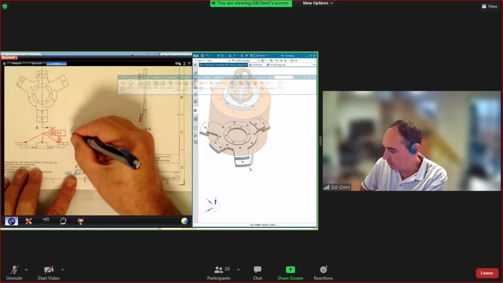
For illustration purposes, Figure 1 shows the mounting of a disc to an adapter.

The design intent is that the yellow disc will be attached to the surface of the blue adapter, centered on the shoulder so that there is freedom left between the screw shank and the hole through which it enters. Figure 2 shows the drawing of the item.

Consider the size and location requirement of the five holes:
The diameter of the hole for the screw to go through, is controlled by a dimension with a tolerance (5x 4.5 H12).
Size is the only variable that affects this requirement.
The distance between each two opposing points must be in the range between 4.50 and 4.62.
On the other hand, in order to ensure that the five screws can be entered through the holes, three variables must be addressed:
- Position in X
- Position in Y
- Perpendicularity with respect to the interfacing plane in the assembly
The physical location of the axis of each of the five holes should be within an area that meets the three conditions for each of the holes.
Position defines a target area, which in this case is a theoretical cylinder of 0.3 mm (in MMC) on a precise theoretical distribution circle with a diameter of 60 and an equal distribution of 72 degrees.
Geometric tolerancing combines the three constraints (X, Y and perpendicularity) into a single variable.
BASIC dimensions determine the position of the tolerance zones (in the example: the distribution circle [60] and the angle [72º]).
BASIC dimensions in the framework of production and inspection, can be considered as the movement of the machine, with the size of the tolerance zone corresponding to the accuracy and repeatability capability of the machine or the process.
In the hole position inspection, the accuracy achieved should be reported. The theoretical position is defined by the BASIC dimensions which do not change, and therefore there is no meaning or value in reporting the theoretical position of the tolerance zone. The deviation in the location of the holes is reported in terms of the diameter of the cylinder, which is centered on the precise theoretical position that contains the entire axis of the hole.
The following table contains entries measured on an item produced according to Figure 2:
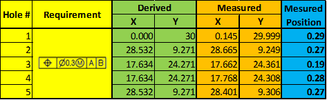
The two green columns (Derived) are the theoretical coordinates of the centers of the tolerance zone evenly divided on a 60-mm diameter distribution circle in terms of X and Y.
The two orange columns (Measured) are the coordinates of the location of the physical axis of the holes (there is a difference between the ASME and ISO definitions of the physical axis of the hole) obtained in the measurement of a specific item.
The blue column is the diameter of the target area, the theoretical cylinder centered on the exact theoretical location that contains the entire axis of the hole.
Based on the actual X and Y values measured, it is difficult to see whether the holes actually conform to the required tolerance.
On the other hand, the blue column shows the deviation in the same terms as the requirement, the diameter of the deviation area. Therefore, with this reporting method it is easy to see whether the holes meet the requirement, and at a glance we can see that all holes are within tolerance.
In summary:
- BASIC dimensions define the desired location and position of the target area in a reference system constructed of datums.
- Deviations are measured by the size of the tolerance area.
- BASIC dimensions can be thought of as the movement of a processing or measuring tool, the shift is always in absolute values (without plus or minus).
- The location deviation is actually the square root of the sum of the square differences between the theoretical coordinates and the coordinates of the physical axis position. For the purpose of accepting (or rejecting) an item, there is no meaning to the differences but to the limits of the functional deviation.
- The BASIC dimensions of the location and position of the tolerance zone remain unchanged, so there is no value in noting them in the measurement report.
Note: For process control, the size and direction of the deviation may be significant, and details may be required in the measurement report.
Questions? Ideas? Suggestions?
Write to us –info@TES-tec.net